
Introduction
A windmill is a man-built structure, used to produce mechanical movement on a helix/shaft system by means of the kinetic energy of the wind. The picture of the modern windmill comes from the 19th century. By that time, windmills started to have great impact on water pumping thanks to a steam pump invented by Thomas Savery, who thought in installing it to watermills (Hills, R. 1996). By last decade of 19th century, the windmill (the Brush postmill in Ohio) was first used to generate electricity, by coupling the windmill shaft to an electrical generator. Nowadays, due to concerns of energy security and sustainability, the windmill has been revived as a medium to produce electricity. By 2008 the installed capacity of wind energy was of 121.188 Megawatts, with a generation of 260TWh, which represents about 1,5% of worldwide electricity production (WWEA, 2008). But it is not in the last two centuries that windmills have been built and used by men. The power of the wind was already noticed in antiquity, when men started to use it to move ships faster and against the water current. Many ancient books, e.g., religious books like the Bible, the Qur’an, etc., describe the use of wind for nautical purposes.
Origin of the windmills: the horizontal windmill
The Persian mill
The origin of the windmill is not precise. The first windmills seem to have been developed by Persians presumably in the 7th century A.D. The oldest reference of Persian mill goes till 644 A.D., when accordingly, the second orthodox Caliph was murdered by a captured Persian technician who claimed to be able to construct mills moved by wind power (Hills, 1996). Persians use it to lift water and grind corn. The mechanism used to lift water remains unknown, but they seem to have used to different mechanisms to grind corn. The first one had the millstones in the upper part of the building and the wind rotor in the lower part, which probably had from eight to twelve sails made of clothing, and four loop holes arranged symmetrically which catches the wind. In the second mechanism the millstone was in the lower part of the building and the sails above. This allowed increasing the area of the sails. The rotor was approximately 5 meter high by 3 meters wide. This windmills had a long life but they required high winds to work. That means, the moveable parts of the Persian mills were heavy and/or with high friction. The configuration of the wind rotor on both mechanisms was horizontal.
The Tibetan mill
It is not clear when the wind mill started to be used in the Tibet. Most likely it was adopted after Buddhism conquered Tibet at the end of the eighth century (Hills, 1996), as prayer wheels were the ubiquitous wind powered artifact in Tibet. These Tibetan Prayer Wheels had a vertical axis with sails formed by curve sheet which allow catching wind in the concave part, and present less resistance to wind in the convex part.
The Chinese mill
There are theories about that Chinese were using windmills more than 2 millenniums ago (Blachford, 2006) but it is uncertain. Most confident sources, shows that the windmill was extended to China approximately at the beginning of 13th century when Genghis Khan captured Yelü Chucai, who knew the Persian windmill, and Ghenghis Kan made him his minister. Those windmills where used in China exclusively to lift water. Those windmills had canvas sails mounted on a pivoting mast, with the ability to be fully open when turning with the wind, and fully retract when turning against the wind. It is difficult to fully and precisely identify when and by whom was the windmill invented. In any case, the first purpose of the windmills was to pump water and grind grain. Although the Persian, Tibetan and Chinese mill were used (and some are still used) for centuries, this type of horizontal windmill had and inferior performance with respect to the later vertical windmills, specially because the former had the characteristic that not all sails where facing the wind at the same time, which decrease considerably the efficiency of the machine.
Introduction of the windmill in Europe: the vertical windmill
The use of the horizontal windmill (like the Persian mill) was also persistent in the Arabic world. Some sources claim that the windmill was brought to Europe by the Turks and the Arabians in the 12th century (Hills, 1996), while others put it during the time of the Crusades (Blachford, 2006). In any case, it came from the Middle East. As for the case of England, which together with the Netherlands have used the windmill intensively since then, saw its first windmill by middle of the 12th century. The windmill has evolved in Europe along centuries, and although the predominant have been the vertical windmill, they also kept developing and improving the horizontal windmill. However, most claims that the vertical windmill did not evolved from the horizontal one. By comparing a vertical windmill with a horizontal windmill and a vertical watermill, it seems most probable that the vertical windmill evolved from the vertical watermill, which was of wide use in Europe.
The Post mill
The post mill is a horizontal axis windmill whose structure is supported by a central massive pivot (the post) in order to allow the structure of the building to rotate and seek for direct wind incidence, as the wind shaft was on horizontal configuration so the sails were constantly facing the wind and allowed longer operation times and higher output power. This was the first mill which showed a brake system. The brakes were placed in the main gear that transferred the mechanical power from the horizontal shaft (directly from the rotor) to the vertical shaft (which drove the millstones). It was widely used in Western Europe and although there are many variations of this windmill basically in the building structure, the basic principle of operation in all of them remains the same. Only worth of mentioning and study, is some English versions (like the Jill Windmill, Fehler: Referenz nicht gefunden) which had a tail pole with blades attached, which allowed to turn the windmill automatically in case the wind changed of direction. The tail also worked as a support of the tower as the wind hitting the blades produces pressure that pushes the whole structure back.
Post mills were deeper than wider, which gave them an esthetic appearance. However, those proportions were given to them in order to minimize obstruction frontal obstruction with the wind. Also, generally the structure was raised from the ground in order to gain height, seeking for stronger and more constant wind, and also to build the blades larger.
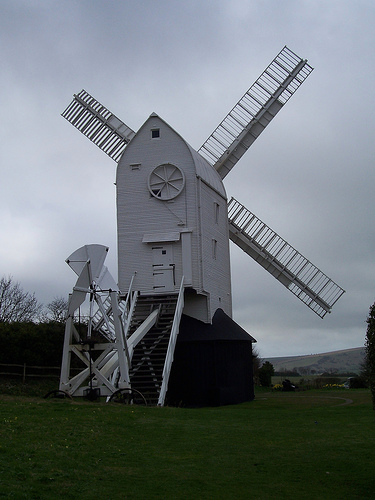
(Jill Windmill (Post mill) located in Clayton, West Sussex in the United Kingdom; Barber, 2009)
The European windmill evolved to the traditional European mill by 15th century, which consisted of a multi story tower made of wood, stone or brick and with a rotor span of 25 meters. Such windmills were able to produce up to 30 kilowatts of power (MSN Encarta, 2008). Europeans have been using the windmill intensively, especially the Netherlands and England in the 18th century, up until the invention of the steam turbine in the 19th century. Great advances were done in the 18th century in the windmill, when special features like speed regulation, through adjustable blade’s pitch and helix self-orientation where of regular use.
The Tower mill
It is a horizontal axis, cylindrical fixed body windmill with a rotating (typically conical) roof to face the sails with the wind. The body (or tower) is made of stone or brick. It started to be developed around 1295 (Langdon, 2005), firstly in France. They also presented a break system for the wind rotor and a tail pole to manually rotate the roof at will. The roof rotates over rollers mounted on a track, and a few rotated by means of a chain wheel and an endless chain. However, this last one was not very popular because the chain provided a way for lightings to get inside to tower, which could cause fires or break the chain and drop the weights, braking violently whatever it might find on its way. If the miller of any other person were inside the mill at that moment, it could be a threat to them.
Many of those windmills have traced in the Netherlands, England, France and Germany. The height of the towers are approximately the same in all of them, and is the same as those that we know today, which may indicate a technology limit for not going further upwards. An important improvement made on the tower mill was the change to a truncated cone form building. The building would be wider on the base and thinner on the top, which would allow for a lower obstruction of the building to the wind. Also, it supposed a cheaper to fabricate, less resources spent and less heavy.
The Mediterranean mill
Although the Mediterranean mill is a form of tower mill, they are classified separately because of some features. First, there were those with full fixed body, usually known as monokairos, but whose sails where always faced to already identified constant air currents (Calvert, 1972). Another one is that with “full-admission axial-flow” sail, typical Mediterranean cloth sail, built on canvas triangular-shaped (like in Fehler: Referenz nicht gefunden), fixed on the wide side to the spar, and the narrow part being attach to the rotor’s axis through a rope. These type of sail have a high low-speed efficiency (they won’t overspeed), and provide good torque.
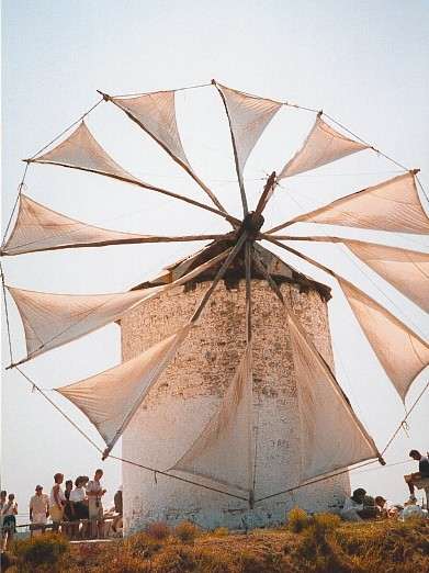
(Windmill in Kos, Greece, with triangular-shaped canvas sails)
The Smock Mill
It is a similar to the tower mill, with the difference that the main body was polygonal (usually hexagonal or octagonal) and constructed on wood. Because of this last characteristic, this type of windmill was lighter than the tower mill, but also was weaker. Also, they proved to be more expansive than tower mills because painting has to be restored annually and rotten wood boards had to be replaced constantly. In strong winds some movement of the windmill’s body could be felt and also on heavy storms water could penetrate through the joints. No surprise that the common practice was to replace them by tower mills when the required materials were available. The Smock Mill also used fantails for automatic control of the roof in relation with the direction of the wind.
The European windmill evolved to the traditional European mill by 15th century, which consisted of a multi story tower made of wood, stone or brick and with a rotor span of 25 meters. From the three basic European windmill types (tower mill, post mill and smock mill) , the tower mill was the sturdiest. The building of tower mills continued up till the 19th century. Such windmills were able to produce up to 30 kilowatts of power (MSN Encarta, 2008)
Characteristics of wind
Although wind behavior is rather unpredictable, it shows certain patterns which depend of seasons, rotation of earth and specific water currents which allows certain predominant air currents to be identified worldwide. Those air currents are mostly constant in the long term, but in short terms they can show themselves with very high speed for hours, but also stagnant. The last case is the non desirable scenario for the harness of wind power. Fehler: Referenz nicht gefunden is a good example for the short term stochastically variation of wind:
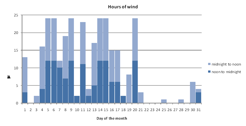
Wind forces on the South Coast of England in January, c. 1900; Hills, 1996)
The threshold winspeed chosen was 4.77 m/s. This figure is not only a good representation of the monthly variation of wind in a specific area, but also it is a proof of the awareness already more than a century ago, to obtain data for design purposes.
The Tail Fan
A great advance done for turning the post, tower and smock mills was that on which instead of having a tail pole, it had a fantail. The fantail was a way to provide rotation of the structure or roof automatically. The fantail was attached to the roof (or structure) at a right angle to the rotor blades, but kept at enough distance from the roof in order to provide momentum and torque when the wind blew frontally (i.e., when the wind blew perpendicular to the main rotor blade of the tower) and provide a force that could move the roof to let the main rotor blade face the wind. However, the rotation movement was not mainly produced because of the momentum provided by the separation of the fain tail with respect to the roof or the structure, but because of a set of gears with high gear ratios whose motion where transferred from the rotation of the fantail to them. Once the rotor blade started to rotate the fain tail was getting no wind or wind parallel to it, so the fantail stopped. This configuration is found nowadays in almost every pump windmill worldwide.
Rotor Blades
The blades are the part of the windmill which uses the energy in the wind to produce mechanical energy. The kinetic energy in the wind hits the blades which by reaction (and thanks to their configuration) produce a rotating movement translating it to the shaft and then to the final use required (stone mills, pump, etc.).
Nowadays, the blades of a wind turbine are fabricated in fiberglass (glass reinforced plastic) and with aerodynamic properties that has been obtained through modeling and simulation with help of today computer’s impressive power, e.g., finite element analysis software is a tool used frequently to foresee different effects on rotor blades prototypes.
Although the basic concept of the rotor blade hasn’t changed a lot, old rotor blades had different construction and designing techniques. The material par excellence in the old days for constructing the rotor’s structure was wood. Once the frame was built on wood on a rectangular shape, it was covered with suitable articles of clothing, which in most cases was canvas. Such sail is known as “common sail”. This same configuration has been used until recently, but the arrangement of the wood framing and the blades has changed over time and over different places.
Blades required a lot of adjustment all through the day in order to obtain the desired performance (Hills, 1996). It is remarkable that the millers generally did not required maximum power. Starting of the rotor was problematic, as the weight of the sales required high torque to produce initial movement. Suitable angles to diminish initial torque were sought for every single windmill. Unluckily, that same angle was almost never the same angle required for maximum power once the rotor started to run. To obtain the desired power, the canvas on the blades had to be adjusted by expanding or reefing it. This procedure required the rotor blade to be stopped.
The typical rectangular blade was perfected by the Dutch, whose dependency on windpower for drainage of their low-lands, pushed them to seek for maximum performance of the windmills. That design is the same that remains till today on most traditional windmills.
The british also made some important improvements, like the one appointed by John Smeaton, who through experimenting came to the conclusion that the blades required a twist from bottom to top in order to gain the most power. Such twist is seen nowadays in the blades of every propeller.
A more practical versions of the common sail were the “spring sail” and the “patent sail” (McNeil, 2002). The spring sail had moveable screen along the frame and were connected all together with a bar attached to a spring. The elongation of the spring was adjusted in order to control the inclination of the screens which would provide control on the pressure of the wind over the blades. This configuration increased the control of the miller over the blades.
The patent sail followed a similar design to the spring sail, but the screens were instead attached to a “striking rod” which had a rack at the end which moved a pinion attached to a chain wheel. The chain wheel had a endless chain where weights were used to produce a downwards force with the purpose to keep the screens closed. Only with enough wind pressure could the screens be opened. This worked as regulatory mechanisms with the characteristic that the weights could be changed while the rotor blade was rotating, improving the functionality of the windmill and its security.
Drainage Mills (or Windpump)
During the 17th century, the people living in the lowlands, who were fighting to keep their lands from being flooded, started to make use of windmills to drain the land (Hills, 1996). Although externally they looked like graining windmills, instead of grind stones they had scoopwheels or Archimedean screw. These last two mechanisms made use of the rotating motion of the rotor blade to rotate themselves. The scoopwheel was a form of waterwheel, taking water from the bottom part and bring it upwards while it was rotating. Likewise, the rotation of the Archimedean wheel allowed to lift water, but rather with a motion parallel to its axis, while the motion of the scoopwheel lifted the water and it was perpendicular to its axis.
Pumped storage microhydro electricy system by mean of a traditional windmill
Although traditional windmills haven’t passed performance test comparable to actual tests who verifies design performance, they have passed through a process of enhancement related to practical experience where the users and/or builders of windmills have been able to make thanks to a process of observation, trial and error.
The introduction of the windmill from one region to another (import of technology) has also played a very important role in the improvement of the traditional windmill. Once a culture get used to one technology it becomes more difficult for them everytime to foresee a new or different way to perform a task, but once a different culture sees a before unknown technology, it could be easier for them to provide feedback on changes that could be done to this technology to make it better.
Nowadays we see the windmills as a big mast with a fan rotating with a horizontal axis, and this way seems to be the logical way for us to build a windmill, but in the beginning it was not like that. People have foreseen the way to harness the power of the windmill through a device who could rotate with a vertical axis. Indeed, this must be a natural reaction of human brain to come with such a device, as it is more similar to other buildings and it is the easiest way to build one. However, through it was noticed that the speed of the wind near the earth surface is many times weaker and slower than the wind at higher altitude, and so new designs trying to separate the fan from the ground and provide better performance allowed to the appearance of what is now known as the traditional European windmill.
The traditional European windmill had its apogee for many centuries during and after renaissance times. This provided a way to get energy and mechanical work and indeed it represented a true relation between man and nature. Just with the arrival of the steam engine, and the discovery of (cheap) oil, the traditional European windmill went into disgrace. But only for a century, because since a pair of decades it resuscitated into a new modern design and a full new name: the wind turbine (sometimes also called, wind generator, aero-generator or wind power unit).
The lack of any test is compensated by reviews, feedbacks and references of preferences which let us know which windmills performed better or which part of it were more suitable for the purpose of producing mechanical work. For simplicity reasons we could divide the windmill in two parts, the mast (or tower) and the rotor (or fan). The mast has been constructed on wood during millenniums up until revolutionary constructor decided to build it on stone, not only to avoid that the wolf couldn’t bring it down by blowing on it, but also to provide a better life span, less maintenance and a stronger structure which could hold a heavier rotor and faster speeds of the rotor. By now, we know scientifically that the tower of the windmill has to be as thin as possible not to intercept the flow of air and loose wind’s kinetic energy. In the past it was already noticed, but the necessity to have many machines inside the tower didn’t allow having thin towers. Today, the tower (or mast) is done as thin as it can hold the rotor without breaking on strong winds. If the windmill were going to be constructed not to mill (which is our case) we can save a lot of space inside the tower, as we need neither the mill nor the reservoir of flour or corn, basic feedstocks of the windmill. Our case only requires the space necessary for gears, a pump and tubes for flow of water. Thus, we can make a real save on space, which will allow a very thin tower, allowing low wind disturbance and save in material to build the tower.
It has been of course during the transition of different ages in human kind, to pass from wood to stone in most building when possible. But this has not been the case for the rotor. A rotor made of stone was not, it is not and it won’t be an option in the near future a good material to build a windmill’s rotor. Therefore, till the end of its apogee was the traditional European windmill’s rotor being built on wood. Of course we shouldn’t underestimate the rotors made on wood. Many improvements were made, and actually in its last days the traditional Europeans rotors were designed with characteristics that are nowadays used on most modern airplanes. But in this area of windmill’s rotors the Mediterraneans were more creative than their European mates, as they had the vista of building the ultimate lightest rotor: a rotor without wood frame but made almost complete only on clothing. This was a definitely revolutionary idea, to use an article of clothing as a mean to build a rotor. The clothing of choice was the canvas. With it, they not only got a lighter rotor, but also they could shape the blades in such a way that improved the capture of wind energy. It is important to notice that the wooden framed rotor were also accompanied with canvas, but the weight of this woodframe is nowadays not viable taking into consideration that the lightest the rotor, the better. The rotor made solely on canvas is better known as jab sail, lacks a frame of wood. Rather, it has a series of radial bows where the canvas is attached. Thus, the lost of weight on the jib sail windmill increases the efficiency of it, a less rigid mast or tower is required and it is more simple to build.
The system projects consist in a windmill, a water pump, a pelton wheel and possibly a water tank. The generation of electricity through a small pelton wheel and generator is better known as micro hydro power, a very attractive system for generation of electrical system due to accessibility and cleanness.
The proposed system is especially suitable for the present trend of distributed generation. The concept of distributed generation is a late response to what has been the regular method of production of electrical energy since Edison’s days, which is the construction of big electrity central which can produce electricity for thousand of consumers. This method has its disadvantages. The biggest are big thermical/ohmic losses in transmission and distribution lines due to high distances from the generator to the consumer. Another one is the fact that the loose of one generator will affect hundreds or even thousands of clients. Distributed generation also improves a nation security issues, by means of decentralizing such a important factor on development of nations as electricity.
The concept of this system is as follows:
- Harnessing of wind power through means of a traditional windmill like windturbine. This will generate a mechanical power on the axis of the windmill’s rotor.
- Use of the windturbine’s mechanical power coupled to a pumping device to pump water to a watertank. This will storage the mechanical power in form of potential energy inside the water tank.
- The stored energy in the tank will be used by letting the water flow to a lower height where a set turbine/generater will convert the energy stored directly into electricity.
- The electrical energy will be distributed to the consumers. If possible, the electrical system can be connected to the regional/national grid, where it could work as a distributed generation energy point.
The system proposed comprises concepts of micro-hydro, pumped storage hydroelectric and microhydro. Such system could provide electricity for many houses depending on the size of each of its components and the wind profile in the area of installation.
In the proposed systems state of the art equipment can be used, however, the idea here proposed is to have a low cost system which could be built and used in areas of low economical input. The main focus here is to use a self-built traditional windmill like wind turbine, to harness the power of wind. The subject of building a traditional windmill with specific design characteristics is out of our scope, indeed this subject merits a deeper study which can be the object of a Thesis. Nonetheless, the feasibility of a traditional windmill nowadays can be found in projects executed by many authors in India, e.g., Tewari et al proposed and built a Greek based traditional sail wing windmill for agricultural purposes in Bangalore. Their windmill had a cost of $900 with a maximum pumping rate of 11,000 liters/hours (Tewari, 1978).
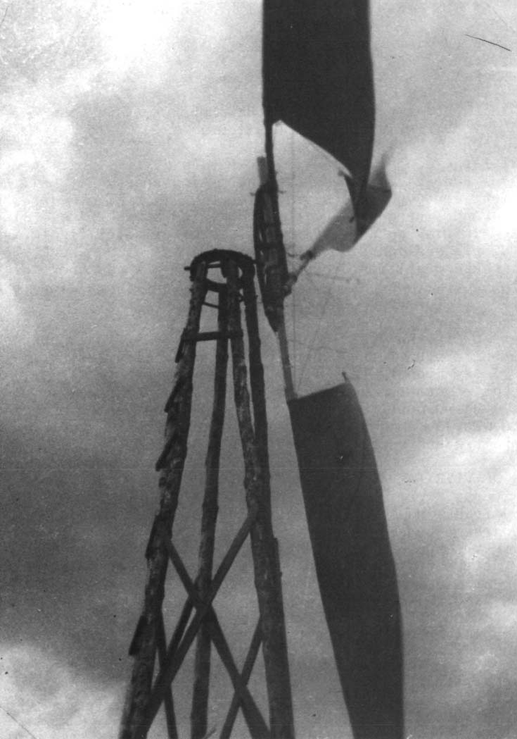
(Sail wing windmill for irrigation in India; Sherman, 1977)
A Water tank could also be built locally with easily available materials. In fact, it is normal in many regions of Africa to have self built water tanks. Moreover, a water tank with a system to catch rainwater could also improve the performance of the systems by enabling more input of water and therefore increase storage energy.
The generator itself is the only assumed device to be bought directly from a vendor/manufacturer. However, this can also be part of a Thesis, to build a electrical generator locally.